Last updated: 12 April 2010
|
Last updated: 12 April 2010 |
Subject:	Analysis of ETX-125PE
Sent:	Saturday, April 17, 2010 14:23:22
From:	johansea (johansea@optusnet.com.au)
The design may have changed since i did this one, as current worm
carriers fit now, but it gives a reasonable idea of whats in there.

WARNING Getting in there is not a job for the inexperienced.
To do it requires making some specialised tools.

Andrew Johansen Melbourne Australia
The following text describes the analysis of a Meade ETX125PE model that was showing very poor pointing ability and no ability to accurately “goto” preset landmarks.
The end result of the exercise highlighted three major sources of error, and the cascading effects found due to trying to overcome them.
Firstly I had attempted drive training and standard 360deg spins to check for encoder errors etc.
This was done with a video feed to ensure accuracy/consistency of results.
The initial drive training was very inconsistent and gave nos around 1800-2000
360 deg spins gave very inconsistent results when reversing but were within 3-5arcmins when spun in a preloaded direction. On watching a video feed, it took around 20 seconds to reverse direction whilst set at speed 3. None of the above is even close to what it should be.
On removing the base cover and attempting to twist the unit on its RA axis, I could see there was about 2deg of slop in the lower clutch assy. After reviewing Mike Weasners site, I found several references to this and its effects, however, whilst it explained part of what I was seeing, it didn’t explain all.
The design of the clutch is relatively poor here and will be described later, but basically, under certain conditions, any small bumps or sticking can cause the clutch to slip in a random manner.
I then put a micrometer onto a tooth on the large 22tooth spur gear on the worm and manually moved the 52tooth output gear from the motor to see how much play there “really” was in the gearbox itself.
Approx half a turn of the 52tooth gear resulted in “measurable” reversing movement on the spur gear.
Very roughly, the encoder has 36vanes and is direct mounted on the motor shaft.
The motor also has a 12tooth gear fitted that drives the 52tooth gear.
As such, ½ a turn of the 52toother = 26 teeth = 2 turns of the motor/encoder
The encoder works in quadrature mode hence we get roughly
2*36*4 = 290 “ticks”
With a drive ratio of 1.368888 ticks/arcsec, this is roughly 212 arcsecs
Drive train results are presented in arcsecs, thus we can deduce that the “minimum possible” drive train will be ~212. It must be noted that this test was done with the gearbox unloaded, so any internal “spring” effects were minimised, but its still a long way from 1800.
I also noted that when the motor was reversed, the gearbox itself was flexing at the collar where the 24 tooth spur gear joined the 8tooth final output gear. Ref Diag 1 next page
This is a well known point for failure in the drive assy, and part of the cause may be due to this effect.
I then started to disassemble the RA motor/gearbox/worm assy.
The worm wheel was hard to remove, as there was no adjustment left in the grubscrews.
Once it had been sprung out, it showed a permanent offset in the supporting O Rings
( ie they didn’t spring back when unloaded ).
Next I removed the gearbox and worm carrier assy from the base. It was then noticable that the worm carrier was VERY stiffly held in its bearings. It took a considerable torque to spin the worm in its bearings, which starts to account for the gearbox flexing noted earlier.
Ie looking at Diag 1 we see a general representation of the final gear teeth meshing mechanism.
T represents the holding torque in the worm. This comprises bearing preload induced torque and also the friction/stiction coming from the worm / wormwheel interface.
F represents the tangential tooth force required to overcome T.
By simple maths F = T * PCD/2
Using a very basic freebody force balance approximation , we can see that the Spur gear on the worm is being pushed up/down on its axle by the same force, ( as is the gearbox, but it is respectively down/up
The Worm has only got the Orings in the worm carrier to spring on, but the gearbox is a cheap plastic housing supported remotely at three points on orings. ( Ref Pic 8 at the back )
As such, the worm axle effectively tries to push the gearbox up /down and the Oring bolts try to hold the gearbox down. This results in a strong bending moment in the plastic support arm around the point where the small gearbox gear fits. This bending moment constantly changes size and direction, hence fatigues the connection at the point between the two axles ( as marked in the Diag above ). This is the point where most gearboxes fail.
Now that the worm was disengaged, I could measure how freely the RA axis spun on its bearings.
( and found It didn’t). It moved very smoothly, but took quite a large torque to get it to spin.
I then measured this using a balanced 250mm lever attached to the base, a piece of string and some nuts and washers. The worm was removed, so the base was freely spinning only on its bearings.
It took approx 183g to get the base to start spinning.
The worm wheel has a PCD of approx 32mm, thus the driving radius is 16mm
Based on simple moment calculations using the above data, we can calculate how much force is required to spin the base by using the worm
0.183 * 250 = F * 16 F = 2.86Kg ( about 6lb )
Thus, the worm carrier needed to be able to take ~3Kg of axial loading to get the base moving.
The worm carrier uses plastic and pressed metal cones for its axial adjustment preloading, and to reduce excessive backlash here, the preload was set very high, thus reducing endplay, but at the cost of increasing the torque required to spin the worm in the bearings
On removing the worm carrier from the base, it was noted earlier that the O Rings weren’t springing back. A big part of this was probably due to the excess preload involved, however, on disassembling the carrier, it was noted that the O Rings were of a very poor construction and were undersized,
Ref below for a comparison, undersize on top, old version on bottom.
The left sides are aligned and the gap on the right shows the difference in dia
I was asked to fit the better quality ones of a proper size ( taken from an earlier model carrier ).
After fitting these and reassembling the carrier, I then found I couldn’t refit the carrier into the base, as there was not enough space left between the casting stop and the worm wheel.
I then measured up the casting of the ETX I was working on and compared it to my 2002 era version ( first version with metal forks ). Ref Pics 9 and 10 at back of document. My version had a totally different clutch mechanism, but the gearbox and worm carrier all measured up identical where it mattered.
My unit had nearly 2mm of clearance between the carrier and the support lugs in the base casting, hence something was wrong
I then accurately measured the base castings
My ETX had approx 35.4mm from the centre of the RA axle to the face of the carrier support lugs
The PE had approx 33.6mm, ie 2mm closer ???
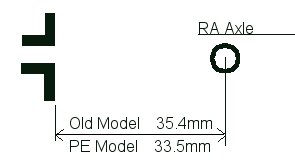
This difference of 2mm is what was preventing the carrier from fitting freely, ( and probably why the undersized O Rings were fitted in the first case, but that’s a guess on my part )
A secondary problem with the undersized O Rings, in conjunction with the high torque on the worm axle is, that when starting to turn, until the worm breaks its stiction and starts sliding, the worm axle can also move up and down in the carrier.
All the above conspired to make for a very stiff RA drive system that operated very erratically
( at the arcsecond level ).
To solve the most basic problem of “why is the RA axis so stiff”, I disassembled the whole base.
The following diag shows the basic RA bearing and loading assy.
Also Ref the pictures section for proper views of the relevant parts.
As per Diag 2, the Forks sit on a greased 2” dia teflon bearing between the base and fork platen.
Then there is a very large dia ball bearing ( 47mmOD x 9mm thk ) in the very top of base itself, and this mainly takes the side loadings transmitted via the worm.
The worm wheel is then fitted below all this and as such is cantilevered ( relative to the bearings ).
The lever arm of this cantilever is quite large, relative to the axial distance between the bearings.
This cantilevered loading layout, in conjunction with the Teflon bearing means the whole system has a bit of inherent “spring” in it, esp the teflon bearing.
Ie, any side load on the RA axle via the worm wheel ( due to high worm/wormwheel preload and axial operating load ) will tend to rock the RA axis out of orthogonality.
UNLESS the whole system is properly pretensioned
Under all circumstances, there will be the worm to wormwheel preload acting, but as the worm turns and attempts to overcome the torque, we also get a large lateral force component via the worm
( For the scope being worked on, rough calcs put the Worm axial loading at about 3Kg.)
Thus, the actual Azimuth direction the final force will act at, ie from F1 to F2, will depend on what the actual worm axial load is currently.
Ie The angle this force swings through will depend on the ratio of Worm Axial load to Worm Preload, and the direction the worm axial load is operating at.
As mentioned above, the only way to prevent the axle rocking with this type of design is to increase the preload, but as the upper bearing is a sliding thrust style bearing, the more preload it has, the harder it becomes to turn, hence catch 22.
What I suspect has happened is that because the worm carriers no longer fit properly ( ie they have a high inherent side preload ), the RA axis has had to be pretensioned to counter this, and this has set a very high starting torque to get the RA axis spinning. This then cascades back through the system and required the Carrier end preload to be increased.
( On my ETX, the wormwheel is mounted “between” two ball bearings, hence sideloading doesn’t affect it, and even when tensioned, it still spins freely )
After a discussion on this fact, it was agreed I would mill about 1mm off the back of the carrier casting, and then preset everything as loosely as possible.
I backed off the Main bearing pretensioner nut to allow the platen to spin freely and reassembled.
Video training now showed a noticable vertical offset when swapping direction, but reversing was now reasonably quick, and drive training was very repeatable at around 600.
By trial and error I then preset the RA bearings progressively tighter until there was no visible shift in Alt when reversing. By grabbing the OTA, I could still spin it easily, and when released, it would spin for about 40deg whilst slowing down by itself, but this was a very subjective test to get right.
Next I completely removed the axial preload in the worm carrier and fitted the worm/wormwheel with a slight preload. I then reset the axial preload by locking the clutch and manually twisting the forks ( very gently ) and watching how much play there was. I tensioned it up till there was only just a little play visible, again subjective.
Reversing directions now worked with no Alt shift, but quite a lot of Az retrograde motion, even at speed 3. To fix this I reduced the worm/wormwheel preload to practically nil, and that fixed it.
Drive training now worked well, but the value had gone up to 700, but this is still reasonable.
Sky testing over two nights and about a dozen aligns showed that aligning worked well and 80-85% of objects were within a 26mmEP. Bench testing using the std Landmark mode also worked.
So the process is
Remove the worm carrier, stripdown
Mill 1mm from carrier and slot the holes
Replace ORings and reassemble
Reset RA torque to minimum value that doesn’t have an Alt shift on reversing.
Set Worm Wormwheel with virtually no preload.
Set Worm carrier endload to minimise movement when base rocked by hand.
Test and tweak if required
A better set of optional fixes ( in ascending order of ease/benefit ) would be
1) machine a groove in the worm wheel and glue in a suitably sized red fibre washer. This will make the upper clutch much more effective, hence removing problems associated with the lower clutch
2) replace the Teflon bearing with a needle roller thrust bearing. The SKF AXK3552 bearing ( plus AS3552 thrust washers ) “looks” like it is almost a perfect replacement. Doing this means the RA axle could be pretensioned suitably, without the downside of increased torque to move it.
3) Replace the clutch “bolt” with a threaded rod. By using a nut at the top, it could be undone there, hence allowing clutch disassy much easier than the current total stripdown.
Note, the new clutch design is fitted to within a gnats kneecap. Referring to Pic2 at the end, you can see how there are packing washers added to the three baseplate screw support pillars. This appears to have been done to increase the distance between the battery compartment and the clutch face so allowing the wires to be routed out. Any mods done to the clutch need to take this into account.
In the above text, I alluded to clutch problems.
There are three major problems in the clutch design ( IMHO )
Diag 3 shows the basic setup
The clutch mechanism starts with an aluminium shoulder on the RA axle stub that acts as a fixed load bearing surface.
Then we have the (cast iron?) Wormwheel which is bolted to a large dia anodised alloy disc.
This assy floats freely on the RA axle stub, and rests against the aforementioned axle stub face.
At the end of the RA axle stub there is effectively a small dia key
Then there is an axially floating clutch plate, ( again anodised alloy ), that fits over the RA axle, and pulls up against the large dia anodised alloy disc wormwheel clutch face
The outer dia of this floating disk provides the primary clutch surface to the wormwheel disk.
At its base, it has a small dia slotted spigot that mates with the key on the bottom of the RA axle stub.
It is this keyway that finally transfers the torque from the floating clutchplate to the RA axle and is the achilles heel of the design.
This keyway has a very small dia and also, due to fabrication tolerances, invariably has a loose fit.
Due to the small dia, a small error in fit equates to a large amount of angular “slop”.
In the unit I worked on, there was about 2deg of slop in RA due to tolerances on the fit of this keyway. However, this shouldn’t have been a problem as there is also a secondary clutch face ( ie wormwheel to alloy stub ). There is no possibility of “tolerance based” slop here, and if designed correctly, it should have provided more than enough holding torque to render the lower clutch totally unnecessary.
What I found was, that as it was an alloy to cast iron joint, the alloy had “polished” smooth over time, and with a bit of grease getting in as well, it rendered that face effectively inoperative ( but not quite).
On cleaning this, roughing with sandpaper and degreasing, the system locked tight, but it’s not a permanent fix as one bit of grease getting in kills it.
Knowing this, we can now go back to the lower clutch, and look at its random operation.
The upper clutch, even when greasy, does supply some holding torque, but this is dependent on how tight the whole clutch assy was done up. On changing direction, the upper clutch would hold until the torsional load on the RA axis got too high, at which point it would slip by the amount of slop in the lower clutch. At that point, the lower clutch starts working correctly and all locks tight until reversing again. I believe this was the major reason for the erratic readings I got when changing direction.
Another source of error is torsional “spring” in the drivetrain itself, but that is more repeatable than the clutch slip.
A secondary problem is that if the end surfaces of the floating clutch plate can ever come in contact with the end of the alloy axle stub, it will also render the clutch semi inoperative .
Ref dimensions A and B in the above diag, as well as the gap “Clutch travel”
A is pretty much fixed and is set based on the assembled Worm + Clutch plate
B = A + Clutch travel
Clutch travel can be a max of 2mm at which point the spigot disconnects, so the tolerances are small.
If as part of tensioning the system, the Clutch travel becomes zero, we are then effectively at the point where the clutch can no longer be tensioned anymore, we are just compressing the RA axle after that.
Hence, if this clearance is too small on assy, we will only be able to get up to a set clutch torque until the ends touch and then it just stays static, no matter how much more we tension the bolt.
Pic 1. Details of opened Base with lower floating clutch plate removed
Note also how there is no clearance between Worm carrier and its support casting
Pic 2. Details of Worm wheel removed. Note polished contact faces. Also
note the packing washers on top of the casting pillars. These appear to be used
to provide more clearance for the wiring where it exits the clutch tensioning
bolt.
Pic 3. Details of how the wiring enters the clutch bolt. The bolt CANNOT be just turned to release the lower clutch plate. The wire must be fed over the top of the bolt as it is rotated. Doing anything else will end up damaging the wires.
Pic
4.
Pic 5. Details of the underside of the Fork Platen showing the Teflon bearing. (3.7mm thick )
Also shows the RA axle stub and clutch key
Pic 6. Details of the Top view of the Base casting showing the simple alloy bearing surface
Note the close coupling distance of the ball bearing
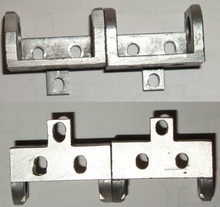
Pic 7. Details of the machined carrier ( left )
The carrier had 1mm removed from its back face and the holes slotted to allow it to fit with no preload.
Pic 8. Details of the O Ring support system for the RA Gearbox. Note that the loaded end of the gearbox ( where the main torque gets applied ) has no nearby support, it all hangs in space.
Ref Pic 1 to see Gearbox overlaid on support )
Pic 9 Details of old style RA Base layout

Go back to my ETX Home Page.